
The following section outlines the steps required to configure RTP, SIP Extension or SIP Trunk recording:
Before any configuration can be set the system needs to be tested to ensure that the monitor NIC has been setup correctly and is capturing the SIP trunk voice traffic. This can be performed using a network protocol analyzer such as the free and open source Wireshark (http://www.wireshark.org/).
The following steps show how to use Wireshark to perform the validation, this was performed using Wireshark v1.8.3, steps may vary with other versions.
Once installed, from the Capture menu select Interfaces and then check the box next to the NIC card listed that is performing the capture. In this example the second NIC listed ("Intel (R) PRO/1000 PL Network Connection") is performing the capture, whereas the first NIC is the main connection to the LAN.
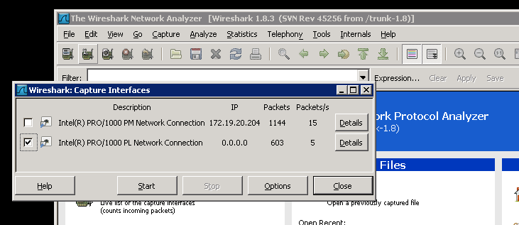
Click on Start and this will begin to show all of the network traffic that is been captured. To filter the traffic to only SIP calls and RTP traffic, enter "sip|| rtp" into the Filter box and click on Apply.
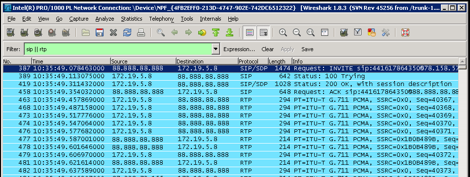
Make an inbound test call and the SIP & RTP traffic should start to be displayed in window as shown. If nothing is shown then either the wrong NIC has been selected or the port mirroring configuration is not correct.
Once the capture has been successful then select Stop from the Capture menu. Then from the Telephony menu select VoIP Calls, after a few seconds there should be a SIP call shown. There may be multiple calls depending on how many calls have been captured.
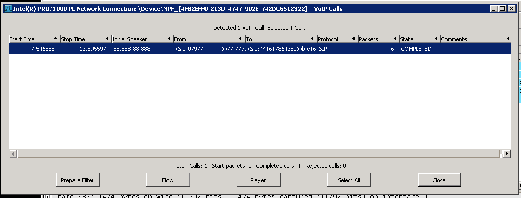
Select one of the calls, click on Player then Decode and the timeline for this call is shown. You should see only two timelines, one for the inbound and one for the outbound legs of the call.
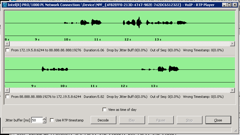
If this matches then the port mirror configuration is correct. Take a note of the device that has been configured as this will be needed when configuring the mirror ports within the call recorder. In this example the device is "NPF_{4FB2EFF0-213D-4747-902E-742DC6512322".

The network interface cards to be used for port mirroring must be selected within the call recorder's configuration. Refer to the Mirror Ports section for more information.
The UDP and TCP ports that are being used for RTP and SIP traffic must be checked within the call recorder's configuration to ensure they match those which are being used by the telephone system. Refer to the Packet Filters section for more information.
The system needs to be able to determine the direction of the SIP call that is been recorded. The only way to know this is by configuring the local IP address of where the incoming SIP traffic is going to and coming from. This needs to be set to the IP address that is shown in the capture.
In this example an inbound call was made and the destination IP address, i.e. the PBX IP address is shown as 172.19.5.8.

To configure this address:
The PBX IP address that needs to be set is dependent on how the port mirroring has been configured. If the mirror connection is internal, i.e. on the LAN, to the network that the PBX is connected to then it would most likely be the internal IP address of the PBX as in this example.
If the mirror connection was made outside of the internal network, i.e. on the public WAN, then the external NAT address would be required.
 |
If this is not set or incorrectly set then some calls may not be recorded. |
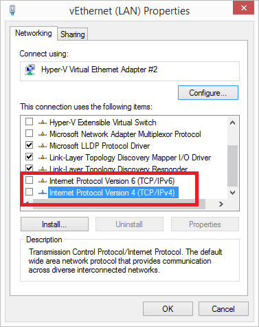
(Optional) The monitor interface adapter that is been used to TAP the RTP traffic can have the TCP/IP protocol disabled. This would then prevent the adapter from receiving any IP address and prevent any access to this adapter other than for the monitor traffic.
From the adapter properties uncheck the "Internet Protocol Version 6 (TCP/IPv6)" and "Internet Protocol Version 4 (TCP/IPv4)" options.
 |
If you are connecting to the server using this adapter then it will disconnect any connections. |
